WZY-R1003 — a 20 × 15 mm, 10W wireless charging receiver
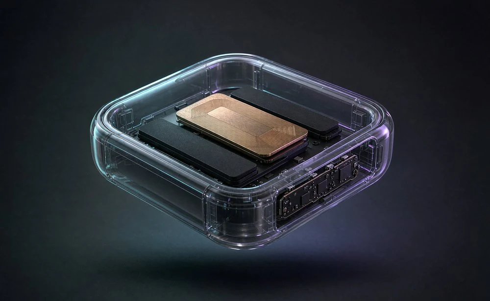
Adding wireless charging to a small product is rarely a power problem. It is a space problem: the battery and the main board already took the room, and what is left is a thin slice. WZY-R1003 exists for that slice — a 20 × 15 mm receiver board, one controller IC, 10W output.
Space is the constraint, not wattage
The question we hear most often is simple: our product is tiny — can it still charge wirelessly? The answer has been yes for years. What used to be expensive was everything around it: structure space, BOM cost, and round after round of debugging.
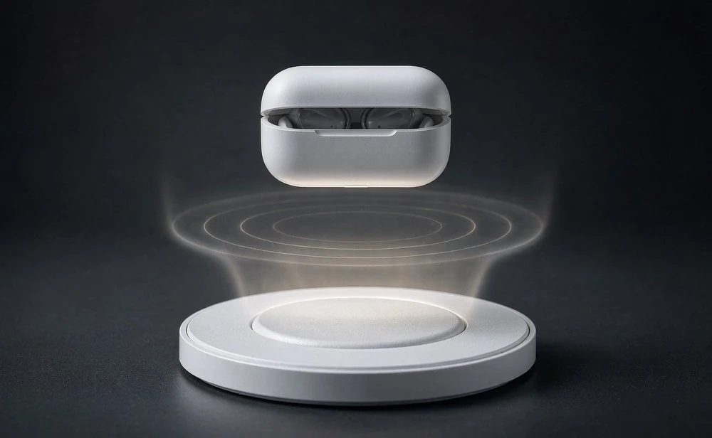
A TWS earbud case is the classic case. The cavity is taken by the battery and the earbuds; what remains for a receiver is often a single thin plate. The tighter the space, the more the integration of the module itself matters.
One controller IC runs the whole chain
Conventional receivers split rectification, regulation and communication across several discrete devices. Every extra part needs board area, pushes the structure around, and adds a variable you cannot easily explain during debugging.
WZY-R1003 takes the other route: from the receiver coil module to the DC output, the whole chain passes through a single controller IC. Fewer external components means a simpler layout, a shorter incoming-material list and less production tuning.
10W, and up to 97% rectifier efficiency
In fast-charge mode the output is 9 V / 1.1 A, exactly 10W. Switched to BPP mode it delivers 5 V / 1.0 A, 5W. Two tiers from one board, so a new project does not need a new receiver.
| Parameter | Rating |
|---|---|
| Output power (fast charge) | 9 V / 1.1 A = 10 W |
| Output power (BPP) | 5 V / 1.0 A = 5 W |
| Max output current | 2 A |
| Operating frequency | approx. 110–205 kHz |
| Ambient temperature | 0 to +85 °C |
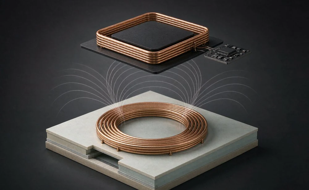
What decides the user experience is heat. The module uses a full synchronous rectifier with peak efficiency up to 97% — every point of loss saved shows up as a few degrees less on the housing at full load. Dynamic rectifier voltage adjustment keeps transient response and full-load efficiency steady as well.
Operating at roughly 110–205 kHz, the module complies with WPC Qi V1.2.4, so it matches common Qi transmitters. You do not have to replace an existing transmitter design to use this receiver.
How small it actually is
The receiver PCB is 20 × 15 mm, 2 mm thick including components; the coil module is 35 × 30 mm and 1.5 mm thick. Those two numbers together decide which products it can go into.
| Part | L × W × T |
|---|---|
| Receiver PCB | 20 × 15 × 2 mm |
| Receiver coil module | 35 × 30 × 1.5 mm |
The coil connects to the board with a stranded lead, soldered at the factory, so the assembly side only has to align and bond. The back of the PCB carries a shield structure that reduces interference with the rest of the device — worth a lot inside a small, metal-dense housing.
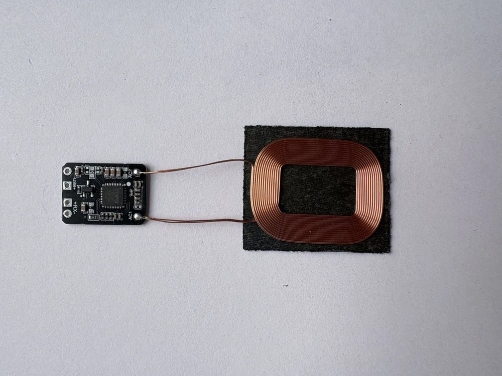
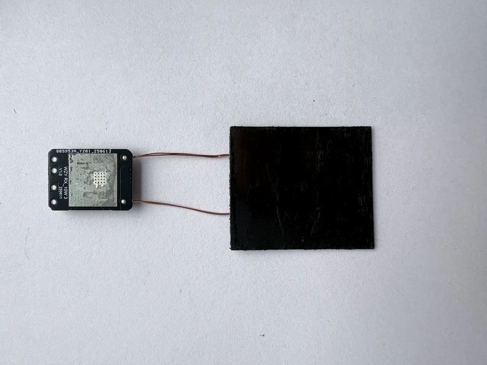
Wiring is deliberately minimal: AC1 / AC2 to the coil, +RX− as DC output to the next stage, plus a reserved USB+ pad for a wired input. Wireless and wired inputs in the same structure give the product maker an extra selling point and a fallback.
Where it already fits
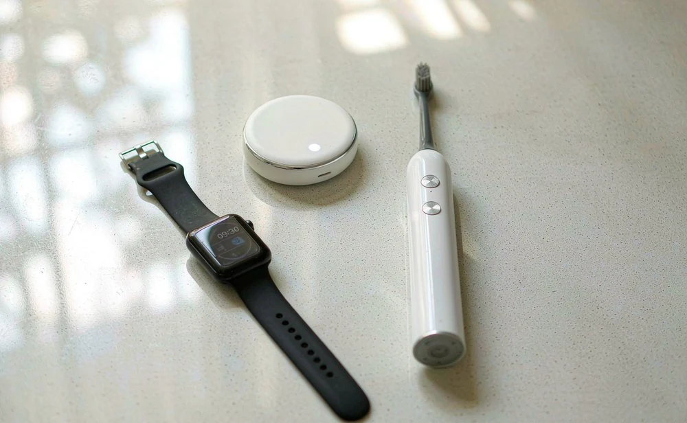
Beyond the TWS charging case, the same module suits MFi trackers, electric toothbrushes, smart watches and bands, and small formats such as e-cigarettes. What they share: they all need a charging port, and none of them really wants one.
Five rules before you design it in
- Bond the coil flat against the module with no air gap; keep the lead short and do not run it parallel to other signal traces.
- Design the structure for a 2–5 mm coupling distance: further away loses power and can trip under-voltage; closer heats up.
- Leave thermal headroom at full load, and avoid running continuously at 85 °C ambient; add copper under the PCB or a thermal path to the housing.
- Keep shields, screws and metal trim out of the coupling area — they cost efficiency and can trigger FOD.
- Handle ESD during assembly and soldering; follow lead-free temperature and time profiles.
Rule 2 is the one most often underestimated. Treat 2–5 mm as a soft parameter during the design review and you will pay for it with a tooling change later.
Related
Need a sample, or want us to check your cavity?
Send the cavity height, target power and annual volume. We reply with a model recommendation and a sample plan.
Request a sample